

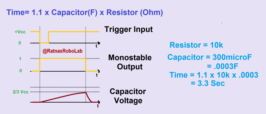
The Monostable Multivibrator has one stable state but whenever the trigger signal is applied then at this moment the output goes into the unstable state.


The time duration for which the output goes into the unstable state can be controlled by the external resistor and capacitor.
555 Modes
Basically 555 timer IC can be used in 3 modes 1. Monostable Mode 2. Bistable Mode 3. Astable Mode.
In this blog we discussed about how 555 Timer can be used as Monostable Multivibrator.
Please support us on YouTube also. Like Share and Subscribe to our channel : https://youtube.com/c/RatnasRoboLab
Monostable Application
Whenever this monostable multivibrator is designed using the 555 timer IC then it can be used in the following applications: 1) Generating Time Delays 2) Frequency Division 3) To generate Pulse Width Modulated (PWM) Output 4) Switching the Relays
555 Timer Pin Diagram
PIN 1 is Ground Pin, Pin 2 is the Trigger Pin, PIN 3 is Output Pin, Pin 4 represents Reset Pin, Pin 5 is the Control Voltage, PIN 6 is Threshold, PIN 7 is the Discharge PIN and PIN 8 represents Power Supply or Vcc.

555 Timer Internal Architecture
555 Timer is divided into 5 parts. First part is voltage divider circuit, second comparator block, third flip-flop circuit, fourth discharge circuit and last output driver circuit.

To learn briefly on it’s Internal Architecture please read our previous blog on this Topic WHAT IS 555 TIMER?
Monostable Multivibrator Circuit Diagram
A LED is connected to PIN3 of 555 Timer with a resistance of 150 ohm. PIN2 is connected to PIN8 with 1K ohm resistor as PIN8 is the Power Supply or VCC also a Pushbutton is connected with PIN2 & Ground. PIN6 is connected to PIN8 with a 10K ohm resistor and a capacitor is connected with PIN6 & Ground. PIN6 is also connected to PIN7 of 555 Timer.

How Monostable Multivibrator Works Internally
If power supply is 9V then Comparator2’s Positive Terminal gets 3V but Comparator2’s Negative Terminal gets 9V as PIN2 is connected to VCC with a 1Kohm resistor.
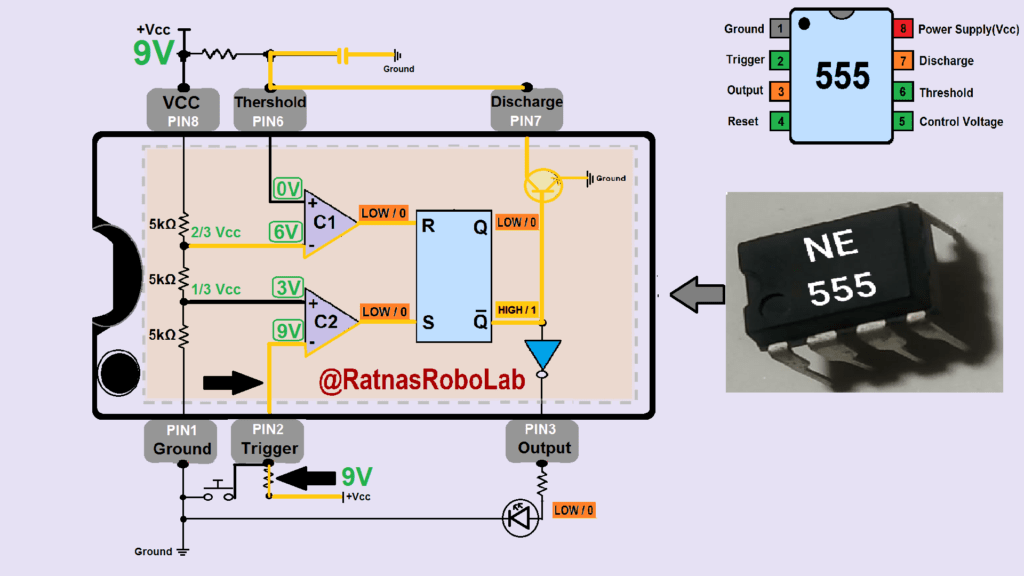
Capacitor State : Discharge
If power supply is 9V then Comparator1’s Negative Terminal gets 6V but as long as the capacitor has no charge (Connecting the capacitor to Ground through Discharge PIN7) Comparator1’s Positive Terminal gets 0V.

Both Comparator’s output LOW, not(Q) becomes HIGH and LED is in LOW or OFF state(One Stable State) until PushButton is pressed.
When PushButton is Pressed
When the PushButton is pressed then at the Negative Terminal of the Comparator2 is connected to Ground. So, Positive Terminal of Comparator2 takes priority and Comparator2’s output becomes HIGH.

Capacitor State : Charging
When PushButton is pressed not(Q) becomes LOW,Discharge Transistor OFF, Capacitor disconnected from Ground and connected with VCC and Capacitor charges up.
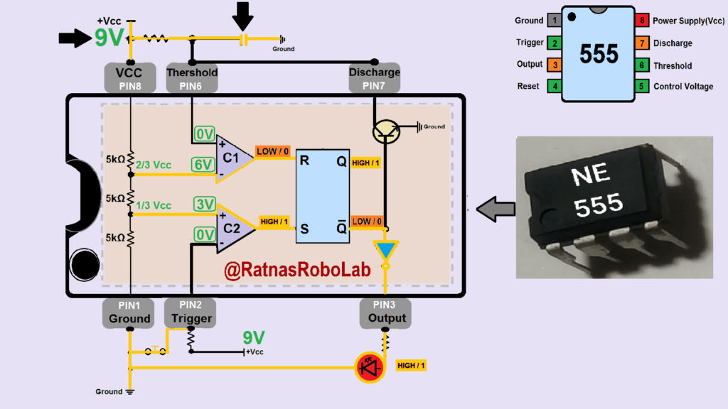
PIN3 output becomes HIGH and LED has been turned ON.
When PushButton is Released
When the PushButton is released then at the Negative Terminal of the Comparator2 is connected to VCC again. So, Negative Terminal of Comparator2 takes priority and Comparator2’s output becomes LOW.
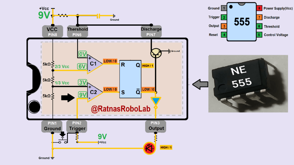
Capacitor State : Charging
When PushButton is released not(Q) stays at LOW state, Discharge Transistor stays OFF, Capacitor still disconnected from Ground and connected with VCC and Capacitor still charging.

PIN3 output still HIGH and LED stays ON until capacitor has a higher than 6V.
Capacitor Discharges
When Capacitor has higher voltage than 6V, Comparator1’s Positive Terminal takes priority and Comparator1’s output becomes HIGH, not(Q) becomes HIGH, Discharge Transistor becomes ON, Capacitor has been connected to Ground again.

Now Capacitor starts Discharging, Comparator1’s Positive Terminal gets 0V, Comparator1’s Negaitive Terminal takes priority and Comparator1’s output becomes LOW but not(Q) is still HIGH, Discharge Transistor is still ON.

Do you want to support our videos ?
https://www.buymeacoffee.com/ratnasrobolab
Support Our Channel By Shopping parts from Amazon !
Product Links
1. 555 Timer IC (5 Pcs) : https://amzn.to/420rhpl
2. Red LED’s (100 Pcs) : https://amzn.to/3n2hAIr
3. Green LED’s : https://amzn.to/3HfO6xi
4. Yellow LED’s : https://amzn.to/3HhfET8
5. Capacitor 10mF (3 Pcs) : https://amzn.to/41OpowA
6. Brass Wire : https://amzn.to/3oKJ8m7
7. Colourful Brass Wire : https://amzn.to/3LyucjJ
8. Solder Iron (7 in 1) : https://amzn.to/3Le8xft
9. Potentiometer 100k (104) : https://amzn.to/3NbAiYG
10. Brass Wire Cutter : https://amzn.to/3NdP2pN
11. Jumper Wires : https://amzn.to/3V6UlJP
12. Varo Board (5 Pcs) : https://amzn.to/41N04a3
13. Resistor 10K Ohm : https://amzn.to/3LAVSol
14. Resistor 150 Ohm : https://amzn.to/423VnZ1
15. Resistor 100K Ohm : https://amzn.to/40KPpLL
Further Readings
If you liked this article, then please subscribe to our YouTube Channel. You can also find us on Instagram, Facebook and Twitter.
READ – CONNECT – BOOST – CREATE